Standalone atMega328 or atTiny 85
Below are the instructions to connect to either a atmega328 or atTiny85
Install USBTiny Programmer drivers from Adafruit (if this have not already been done)
- download driver from here http://learn.adafruit.com/usbtinyisp/download, make sure you have the right driver, unzip somewhere then plug in the USBtiny programmer. Then follow the install instructions.
- Now you should be able to see this in device manager ( under LibUSB-Win32 Devices), and when running avrdude -c usbtiny -p m328p you should get a connection. Full instruction here, http://learn.adafruit.com/usbtinyisp/drivers.
- If you cannot connect to avrdude or the board then you might have a faulty chip or drivers are not installed correctly.
Uploading Code To atMega328 and tiny without bootloader :)
- Setup standalone, there instruction are pretty good, http://arduino.cc/en/Main/Standalone, but remember 1) that you don't have to have the crystal installed. And if you put in a new chip that is blank then you need to make sure the fuses are OK, only really need this if you put in the crystal, see below. 2) it plays to use the little board to connecting the USBTinyISP to the chip as the pin that says "This image is a view from the bottom..." is missing leading and to me looks like the view from the top of the connection 2X3 connector.
- check with AVRDude that you can connect to chip. If you cannot do this then either the chip is not right or the USBTiny is not right.
- AtMega328 check connection use avrdude -c usbtiny -p m328p
- AtTiny85 check connection use avrdude -c usbtiny -p t85
- Compiling Code is done in Arduino IDE, make sure you have selected the correct board.
- Find the location and change directory in command line, then
- Set fuses (see below) if these have not been set.
- Then upload the hex file using the following format, with correct hex file name : avrdude -c usbtiny -p m328p -U flash:w:test_leds.hex
Fuses for Atmega328 and AtTiny85
- Fuses need to be correct, if the chip has been blank, the following are what needed if you have a 16MHz crystal installed. Otherwise the default for 1Mhz internal clock is just as the chip is (not sure what the actual code is).
- AtMega328 fuses, as per the Arduino enviroment i.e. with external clock for
avrdude -c usbtiny -p m328p -U lfuse:w:0xFF:m -U hfuse:w:0xDE:m -U efuse:w:0x05:m
- background information on fuses can be found here link .
- defaults fuses for arduino environment can be found here, http://www.codingwithcody.com/2011/04/arduino-default-fuse-settings/
- (Default fuses are avrdude -c usbtiny -p m328p -U lfuse:w:0x62:m -U hfuse:w:0xd9:m -U efuse:w:0xff:m )
- Reading and writing fuses, http://heliosoph.mit-links.info/arduinoisp-reading-writing-fuses-atmega328p/, basically use avrdude -c usbtiny -p m328p -v, the -v will give a lot of information but the last bit are the current fuses. default one from chips that have had nothing done are lfuse:62 hFuse:D9 eFuse 07
- Fuses for atTiny85 so you can use pin 1 (reset0 as IO, remember this is advanced and you if you want to program the chip again you need to use high voltage programming. ??? link you can change the internal clock speed.
background information can be found here, http://www.ladyada.net/learn/avr/avrdude.html.
Uploading to the Atmega and installing bootloader - Starting from a blank chip
Step 1 - Setup Board
1) Follow http://arduino.cc/en/Main/Standalone, if you don't use a crystal then might be issues in selecting the right bootloader, so easy thing stay with crystal.
2) USBTinyISP provides the Vcc of 5V and this can be connected rather than having to have another power source.
Step 2 - Installing bootloader with IDE
First you need to do this using the USBTinyISP connection, and you can do it in the IDE, means that you don't have to think about fuses and only limits the options a bit.
Note - the adafruit USBTinyISP will supply the power but some ISP programmers don't, which in my book is a pain.
Equipment to use - USBTinyISP
1) Connect the ISP programmer as discussed and documented above, or refer to http://arduino.cc/en/Main/Standalone, But remember that it plays to use the little board to connecting the USBTinyISP to the chip as the pin that says "This image is a view from the bottom..." is missing leading and to me looks like the view from the top of the connection 2X3 connector.
2) Select the correct board and the programmer.
3) press up tools/ burn bootloader - if you have led 13 connected this will turn off when bootloader is done.
4) note - this can probably be done using avrdude directly and much quicker but need to look into that. See below "bootloader the hardway"
problems connecting
1) goto command line and check things with AVRDude - AtMega328 check connection use avrdude -c usbtiny -p m328p, this will tell you if the ISP can connect with the chip and if the chip is not working. That is gives more information than the IDE.
2) make sure that the reset pin for ISP programmer is connected directly to the Reset pin and that the reset pin is pulled high.
BootLoader the hardway
ok so something we need to know about the bootloader, https://learn.sparkfun.com/tutorials/installing-an-arduino-bootloader/uploading-code---hard-way, hex file I used was C:\Arduino\arduino-1.0.5\hardware\arduino\bootloaders\atmega8 but I didn't get it to work, might have been something wrong with the board that I was using as it had already blown up and only ISP programming was working properly. (as you can see first attempt didn't work, but the easy way work if not a bit slow AP - come back and retry this).
a) - set the fuses - atmega328p via USBtinyISP
avrdude -b 19200 -c usbtiny -p m328p -v -e -U efuse:w:0x05:m -U hfuse:w:0xD6:m -U lfuse:w:0xFF:m
b) load the bootloader hex file - There are two bootloaders that we can load
Arduino UNO Bootloader(recommended)
general avrdude command: avrdude -b19200 -c usbtiny -p m328p -v -e -U flash:w:hexfilename.hex -U lock:w:0x0F:m
hex (bootloader) File location : C:\Arduino\arduino-1.0.5\hardware\arduino\bootloaders\optiboot
How to:
* open command line and change directory: cd C:\Arduino\arduino-1.0.5\hardware\arduino\bootloaders\optiboot
* in command line : avrdude -b19200 -c usbtiny -p m328p -v -e -U flash:w:optiboot_atmega328.hex -U lock:w:0x0F:m
time to load is 180seconds - 3 minutes (in IDE takes 3 minutes also but you don't get to see the progress, but much easier to select the board, no mistakes there).
Note - if bootloader is successful then pin 13 should flash. Plus all the other messages that say things have worked when uploading the bootloader of course.
Arduino Duemilanove
general avrdude command: avrdude -b19200 -c usbtiny -p m328p -v -e -U flash:w:hexfilename.hex -U lock:w:0x0F:m
hex (bootloader) File location : C:\Arduino\arduino-1.0.5\hardware\arduino\bootloaders\atmega
How to:
* open command line and change directory: cd C:\Arduino\arduino-1.0.5\hardware\arduino\bootloaders\atmega
* in command line : avrdude -b19200 -c usbtiny -p m328p -v -e -U flash:w:ATmegaBOOT_168_atmega328.hex -U lock:w:0x0F:m
Step 3 - Uploading Code in IDE Using FTDI
Equipment to use - prefer to the the sparkfun FTDI as i know it works with the pro mini.
1) Make sure that the FTDI that you are using is the right voltage for you chip. Or just connect up ground and use external power supply.
2) (might not need this) Make sure that the reset connection to the USBTinyISP has been removed.
3) Connect up FTDI friend per instructions http://arduino.cc/en/Main/Standalone, with the addition that a 0.1uF capacitor needs to be put between DTR and the reset pin (which is pulled high).
4) Select the right board and then upload. Now you will have a fullying working IDE. Wonderful stuff.
note - the new version from 018 should be able to use can use RTS instead of DTR but I don't have a FTDI board to test this out on.
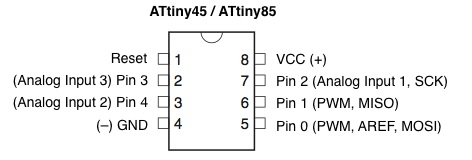
Getting the Tiny85 working
nice image of the pin out the attiny85
http://highlowtech.org/?p=169 ,
I use avrdude to upload it and the arduino environment to make it. I also use the rullywow.www 85 board to program with, just save connecting all the wires and has a nice light and reset on it.
1) check that the chip connects and is working using : avrdude -c usbtiny -p t85
2) in arduino IDE switch to 1Mhz 85, or if you have the fuses different switch to the 8Mhz chip
3) compile the code and then in command line change to the directory that its compiled to, will be something like :C:\DOCUME~1\User\LOCALS~1\Temp\build2905379779008379358.tmp
4) from the command line upload the code using something like: avrdude -c usbtiny -p t85 -U flash:w:Blink.cpp.hex
Burning Fuses for 8MHz clock
1) Adafruit has a link to a fuse calculator, http://www.engbedded.com/fusecalc/
2) uncheck option to divide internal clock by 8
3) these are the settings:
-U lfuse:w:0xe2:m -U hfuse:w:0xdf:m -U efuse:w:0xff:m
So copy and paste this into command line (8Mhz): avrdude -c usbtiny -p t85 -U lfuse:w:0xe2:m -U hfuse:w:0xdf:m -U efuse:w:0xff:m
1MHz : avrdude -c usbtiny -p t85 -U lfuse:w:0x62:m -U hfuse:w:0xdf:m -U efuse:w:0xff:m
Issues
1) sometimes the circuit will not allow the code to upload. So will need to unplug the chip and upload then plug it back in.
2) make sure the the ide is set to the right chip
getting servo working on attiny85
https://www.servocity.com/html/how_do_servos_work_.html - 20ms period, pulse width represents angle. This changes with servo but for example hs55 600ns is zero degrees and 2400ns is 180 degrees.
http://www.cunningturtle.com/servo8bit-library-version-0-6-released/
ok this version and v7 are not working darn. try another servo library
http://letsmakerobots.com/node/36523
ok this works and looking at the code and thinking more about it, its actually not that hard. I could write code that does what I want quite easily :) i.e. servo with speed control.
http://www.jcopro.net/2013/05/21/simple-attiny-servo-control/
